MAX7219 8*8 Dot Matrix Module Microcontroller Module Display Module MCU LED Display Control Module For Arduino 5V
- I am an international seller
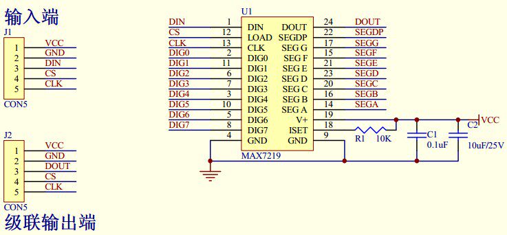
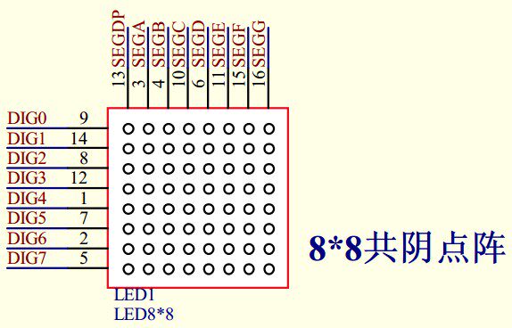
Our shop sells the most popular 3C consumer electronics products,such as mobile phone accessories,computer accessories,game peripherals,smart wearables,and follow the most popular fashion trends. If you like our products,please follow us,become our follower and fan.We will provide you with the most popular products to satisfy your fashion shopping experience.Package : Moduleis_customized : YesModel Number : MAX7219 8x8 64 Dot Matrix ModuleOperating Temperature : -Dissipation Power : lowSupply Voltage : 5VApplication : ComputerCondition : NewType : Voltage RegulatorBrand Name : EC Buying : Mainland ChinaSmart Electronics Experiment : Switch And Sensor For Arduino STM32The MAX7219 is an integrated serial input/output common-cathode display driver that connects a microprocessor with an 8-digit 7-segment digital LED display, as well as a bar graph display or 64 individual LEDs. It includes an on-chip B-type BCD ener, multiple scan loops, segment word drivers, and an 8*8 static RAM for storing each data. There is only one external register used to set the segment current for each LED.A convenient four-wire serial interface connects all common microprocessors. Each data can be addressed when updated without overwriting all displays. The MAX7219 also allows the user to choose to ene or not ene each data.The entire device contains a 150μA low-power shutdown mode, analog and digital brightness controls, a scan limit register that allows the user to display 1-8 bits of data, and a detection mode that turns all LEDs on.Only 3 IO ports are needed to drive 1 dot matrix! Dot matrix display without flicker! Cascading is supported!Module :1. A single module can drive an 8*8 common cathode lattice2. Module working voltage: 5V3. Module size: length 5cm X width 3.2cm X height 1.5cm4. With 4 fixing screw holes, the hole diameter is 3mm, which can be fixed with our M3 copper column5. The module has an input and output interface, supporting multiple modules cascadeWiring Instructions:1. The left side of the module is the input port, and the right side is the output port.2. When controlling a single module, you only need to connect the input port to the CPU3. When multiple modules are cascaded, the input terminal of the first module is connected to the CPU, the output terminal is connected to the input terminal of the second module, the output terminal of the second module is connected to the input terminal of the third module, and so on. ..Take 51 microcontroller as an example:VCC → 5VGND → GNDDIN → P22CS → P21CLK → P20VCC power supply is positive 5V; GND power supply is negative;DIN pin serial data input port, when the clock rises, the data is loaded into the internal 16 bit register;CS pin chip selection terminal, which is the low level serial data loaded into the shift register, and the last 16 bits of the continuous data are locked at the rising edge of the CS terminal;CLK pin clock data input terminal, the maximum rate is 10MHz. At the rising edge of the clock, the data is moved to the internal shift register, and at the falling edge, the data is output from the DOUT terminal;The DOUT pin is cascaded with the serial data output terminal. The data input from DIN is valid at this terminal after 16.5 clock cycles. When multiple MAX7219 are used, this terminal is convenient for expansion.1. The left side of the module is the input port, and the right side is the output port;2. When controlling a single module, only the input port needs to be connected to the CPU;3. When multiple modules are cascaded, the input terminal of the first module is connected to the CPU, the output terminal is connected to the input terminal of the second module, the output terminal of the second module is connected to the input terminal of the third module, and so on


/product/31/8308662/1.jpg?6640)


/product/31/8308662/1.jpg?6640)